Abstract
This paper describes back-to-back accelerometers and the process of using these accelerometers to calibrate other sensors. The process is described using a step-by-step tutorial including customizable test setup, required equipment for calibration, and the other considerations that need to be made when conducting calibration procedures. The paper logically walks the reader through the calibration process as if they were using a VR9500 vibration controller and VibrationVIEW software from Vibration Research Corporation. Other topics include basic accelerometer properties and definitions, piezoelectric sensor limitations, and miscellaneous pitfalls associated with accelerometer calibration.
Accelerometers
An accelerometer is an electromechanical device that is used to measure acceleration. They are used for many applications such as modal analysis, Environmental Stress Screening (ESS), Health and Usage Monitoring Systems (HUMS), Predictive Maintenance (Industrial Monitoring), and also vibration testing. A vibration technician may see several hundred accelerometers during one day if they are conducting high channel count vibration tests!
Accelerometers widely vary in physical size, weight, color, shape, application, etc., however, one thing that they all have in common is the need to be calibrated regularly.
Accelerometer Calibration
Accelerometers must be calibrated yearly to ensure the accuracy of the data they are collecting. Calibrations are generally acceptable for a one-year term then they must be calibrated again. This process must be continued for the entire life of the sensor.
There are several methods that can be used to calibrate accelerometers and the process can take place at a variety of locations. For example, sensors can be sent to the manufacturers for calibration, calibration can be done in-house, or sensors can be sent to an outside laboratory for calibration. Regardless of where the calibrations take place, the most common method and the focus of this paper is the back-to-back method of calibration. Other methods include random vibration accelerometer calibration and close proximity accelerometer calibration, neither of which are described in-depth in this paper.
Accelerometer Limitations and Considerations
When discussing limitations associated with certain accelerometers, it is important to make the distinction between dynamic and static measurements. A static measurement is a physical quantity that is being measured but it changes very slowly or does not change at all. An example of a static measurement is gravity. If you were to measure gravity today and then measure it again tomorrow, the measurement would be the same. Gravity is not something we have to check each morning when we wake up to be sure that we can keep both feet on the ground.
The opposite of a static measurement is a dynamic measurement and by definition, a dynamic measurement is a physical quantity that changes rapidly over time. A few examples of dynamic measurements include acceleration, force, and pressure. When we talk about accelerometer calibration we are talking about dynamic measurements and it is important to understand this difference and also the limitations that result from the nature of dynamic measurements. Sensitivities vary across the frequency range and there is an element of uncertainty associated with the process.
An accelerometer is a spring-mass system and by definition, every spring-mass system has a resonance. An accelerometer is used to determine the resonant frequencies of products but the resonant frequency of the sensor must also be considered. The high-frequency response limit of a sensor is a function of the sensor resonance and should be noted. The sensor resonance can be found on the datasheet from most accelerometer manufacturers and a general rule of thumb is to make sure that the resonant frequency of an accelerometer is at least 5x the highest frequency you are measuring. For example, an accelerometer has a stated resonant frequency of over 32 kHz and a technician is required to calibrate up to 5 kHz. This is well within the general guideline of 5x greater than the resonant frequency and the calibration values can be trusted.
Some of the most common considerations when conducting accelerometer calibrations include temperature, noise, and electrostatic fields. The temperature should be consistently monitored to ensure accuracy and also easily visible on any calibration certification related to a sensor. Noise within the laboratory should be minimized because sensors can pick up noise and introduce it into the readings. This adds to the uncertainty of the calibration of the accelerometer. Electrostatic energy should also be minimized to increase the accuracy of calibrations.
Several other error sources include pressure, poor cable or sensor attachment, and ground loops within a system. Each of these items must be considered and reduced to the lowest level possible to ensure the most accurate calibration procedures.
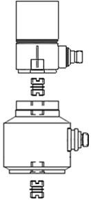
Figure 1: Back-to-back accelerometer schematic
Back-to-Back Calibration
To calibrate a vibration accelerometer is to accurately determine its sensitivity (in mV/g or pC/g) at various frequencies of interest. The ISA-approved back-to-back comparison method is probably the most convenient and least expensive technique. Typically, back-to-back calibration requires coupling the test accelerometer directly to a (NIST) traceable double-ended calibration standard accelerometer and driving the couple pair with a vibration exciter at various frequencies and acceleration (g) levels. The assumption is that since the accelerometers are tightly coupled together, both will experience exactly the same motion, thus the calibration of the back-to-back standard accelerometer can be precisely “transferred” to the test accelerometer [1]. This is an ISA Approved Method of calibration and the preferred method of calibration for the majority of accelerometers. The useful frequency range using this method is 10 – 10,000 Hz, and +/- 2%.
Vibration Research Calibration Package
Vibration Research offers a turnkey system that gives users the ability to perform calibrations within their facility. The average cost to send out a sensor for calibration is about $50 to $75 per axis and these prices can add up quickly with a large number of accelerometers. The accelerometer calibration package from VR includes a vibration controller (VR9500), VibrationVIEW software, a shaker, an amplifier, and a back-to-back accelerometer (see Figure 2).
With this equipment, there is no limit to the number of accelerometers that can be calibrated and there is no recurring cost. The process is automated and takes less than 5 minutes per sensor! The VR9500 is connected to the PC via an Ethernet cable and the VibrationVIEW software allows the user to create a custom profile or use the standard built-in profile from Vibration Research. The back-to-back accelerometer is connected to channel 1 of the controller and the sensor that is to be calibrated must be connected to channel 2. The drive output of the controller is connected to the amplifier using a BNC cable, and the amplifier is connected to the shaker. This completes the closed-loop control necessary to perform such a calibration (see picture below).
Once the system is properly set up, the user can navigate to the default test profile within VibrationVIEW, make any desired changes to the test profile, and simply press the start button. VibrationVIEW software utilizes HTML forms to allow users to enter pertinent information before the calibration procedure begins. This information can then be pulled into the calibration certification report that is automatically populated upon the completion of the test.
The default test profile from Vibration Research is a series of dwells from 5 to 10,000Hz. The calibration value is calculated from the dwell at 100Hz. This is the first and longest dwell of the test profile with a duration of 15 seconds. If an accelerometer is calibrated at an outside facility it is returned a new sensitivity prominently displayed on the calibration certificate and it is likely also calculated at 100 Hz. If for any reason a different frequency is preferred, it can be changed within the VibrationVIEW software.
The next step in the process is a series of 5-second dwells from 5 to 10,000Hz. These frequencies are also completely customizable so any combination of frequencies can be added or removed from the list. When each dwell has been completed a report will automatically be created.
The results from the calibration procedure are displayed numerically and graphically in the report. The response of an accelerometer is not perfectly linear so responses and tolerances will vary depending upon frequency. The standard document (which is also customizable) displays the phase and amplitude response of the newly calibrated accelerometer along with a chart showing each frequency dwell and the deviation at that frequency.
VibrationVIEW software has the ability to read and re-write the TEDS data on a sensor and the user will be asked if they would like to do this once the test has been completed. TEDS is a relatively new technology within the accelerometer industry and the acronym stands for Transducer Electronic Data Sheet. If a transducer has TEDS capability, users can connect the sensor to the controller and simply click ‘Read TEDS.’ The controller will send out a signal to the accelerometer and automatically retrieve and enter the correct sensitivity, manufacturer, make, model number, etc. into the corresponding field within the software. This technology eliminates mistakes when entering sensitivities and saves time by not having to search for the correct sensor calibration certificate each time a new sensor is used. Sensor calibration does not get much easier than that – automatic report generation and the ability to update TEDS information all within your own lab!
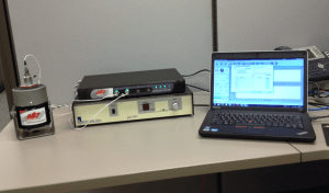
Figure 2: Accelerometer calibration setup with shaker, amp, accelerometers, controller, computer
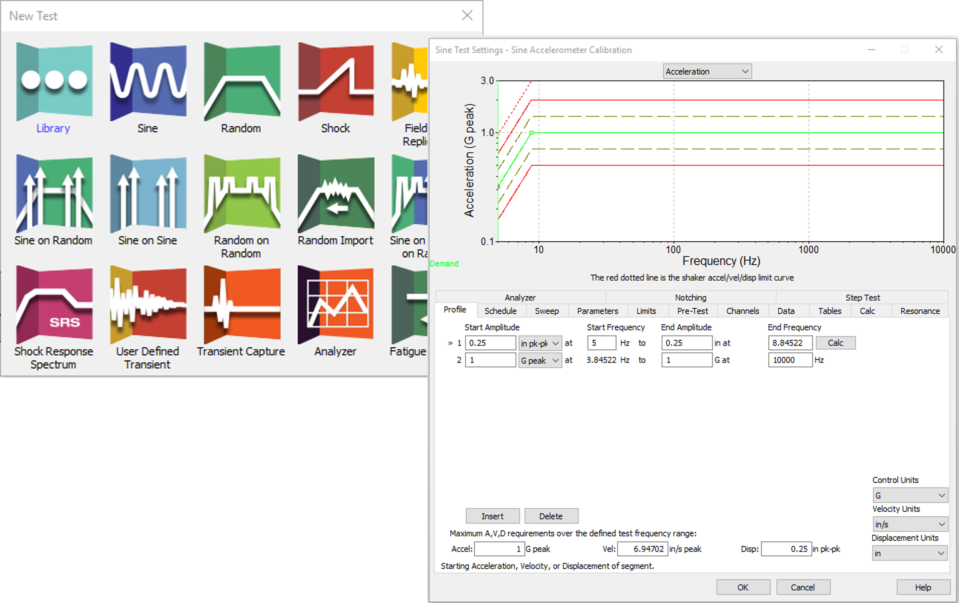
Figure 3. New test and Sine test settings for sine accelerometer calibration.
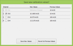
Figure 4: “Save new calibration values?” screen
Conclusion
Accelerometers are an essential component of vibration and calibration is necessary to ensure that they continue to function properly. The accelerometer calibration package from Vibration Research is a cost-effective and proven reliable way for companies to bring the capability in-house and lead to significant cost savings!