Drive multiple shakers with control of the output phase
Test oversized products or replicate field assembly by synchronizing two to four shakers with the same test profile. The VR10500 vibration controller can perform multi-loop with phase control in the Sine, Random, Shock, and FDR test modes.
Multi-loop phase control synchronizes two or more shakers moving on the same axis while maintaining phase through level changes. It is achieved by using 2, 3, or 4 outputs of a VR10500. The drive and COLA outputs from one controller drive multiple shakers with the same test profile. The result is a synchronized set of shakers, ideal for full system testing of a larger device.
Test Systems
A multi-loop test with phase control requires a VR10500 with multiple loops enabled. The primary VR10500 controller must drive all outputs, but the system can have stacked controllers for more than 16 inputs (up to 512).
The Sine, Random, Shock, and Field Data Replication (FDR) test modes can run 2, 3, or 4 output drive loops simultaneously but have different control capabilities.
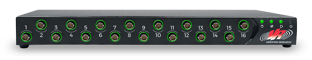
VR10500 I/O Unit
Vibration Research’s high channel count control hardware for vibration and shock testing. Scalable to 512 channels and compatible with all electrodynamic and servo-hydraulic shakers. Features include up to 256kHz sample rate and 4 outputs for multiple shakers.
Random
Run random tests with Gaussian amplitude distribution.
104,000 lines of control (26,000 with the VR9500)
Supports over 9,999 breakpoints, suitable for virtually any test specification
Each control loop can have a unique test profile and limits
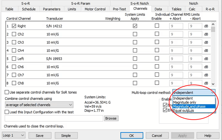
Includes independent, magnitude and phase, magnitude-only, and equal outputs control
“Run For” schedule level can have an independent modifier
Field Data Replication
Playback a recorded time-history file as a control reference; the output phase is synchronized.
Sine
Run a single frequency sine tone at a defined amplitude and time.
Each control loop uses the same profile, but the user can adjust the phase angle between the two outputs (±360 degrees)
Control how fast the phase control loop updates in Magnitude and phase control
Limit how fast the phase between the output channels changes
Includes magnitude and phase, magnitude-only, and equal outputs control
Shock/SRS
Run an industry-standard pulse or a user-defined transient pulse; the output phase is synchronized.
Graphing
Graph settings include a control loop section, and the user can select which control loop demand, control, tolerance, and abort traces to plot. Any loop can be the reference for the transmissibility plot.
Dual-loop Phase Control
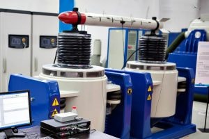
Dual-loop phase control is a type of multi-loop phase control. Two shakers are in a push-push configuration if they face the same direction. When facing one another, they are in a push-pull configuration.
How-to Run Dual-shaker Testing
Oversized or heavy items may be too large for a single shaker. Learn how to set up a Random and Sine dual-shaker test to run in phase with this technote.
Multi-loop Random Test Using COLA
To perform multi-loop control in Random using the COLA output, the controller:
Must include the Dual-loop Random Control key
Must not include the COLA key
Test Specifications
Dual shaker control in Random includes four control methods:
Equal outputs: outputs are always the same magnitude and phase (all shakers receive the same drive signal)
Independent: drive outputs are always the same signal; COLA outputs are disabled
Magnitude only: drive output controls the magnitude of the first control channel; COLA output controls the magnitude of the second control channel
Magnitude and phase: magnitude and phase of the drive output are based on the first control channel; magnitude and phase of the COLA output are based on the second control channel
Additional Features
Combine control channels using the average of selected channels
Apply the memorized drive feature
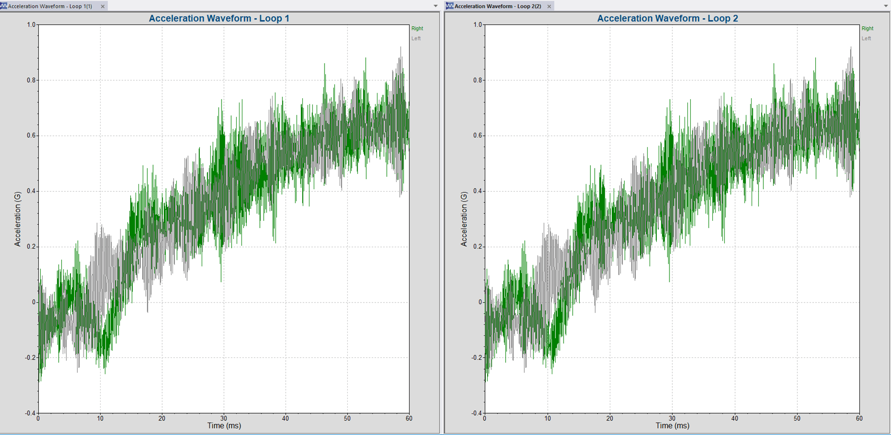
Plotting Multiple Loops
In Magnitude only or Magnitude and Phase control, the COLA trace is available on the following graphs: